Important: Please update your ECU software before plugging in the Traction Control Module.
Warning: This product interfaces with wheels speed sensors used by anti-lock braking (ABS). If ABS is present on your vehicle then you must follow the installation instructions and notes otherwise ABS may be inactivated. Installation should be performed by a person experienced in automotive electrics. Testing should be performed in a controlled environment. Read and understand the instructions and help guidelines before using this device. |
Step 1 - Update your ECU software.
Update your SManager / KManager / FlashProManager software by downloading from the Hondata website. The Traction Control module is configured from a window within SManager / KManager / FlashProManager.
If you are not using Hondata ECU software then there is a standalone version of TractionControlManager. Only use this if you are not using SManager / KManager / FlashProManager.
Step 2 - Register your Traction Control.
If using SManager / KManager / FlashProManager, use 'Window' -> 'Traction Control' to open the Traction Control window.
Plug in the Traction Control module to the laptop. USB drivers should be installed automatically.
Fill out the owner's details on the 'Owner' tab. Update these changes to the Traction Control module, and then register the Traction Control with Hondata.
Step 3 - Determine where to place the Traction Control components.
Traction Control Module
The traction control module should be placed near the ECU. If the ECU is under the hood or exposed to weather, the traction control module should be placed as close as possible to the ECU but somewhere dry.
ABS / wheel speed sensors
The traction control module needs to be wired to the wheel speed sensors. Usually the best way to do this is to connect to the wiring harness to the ABS wiring close to the ABS unit.
Switch Module
The switch module should be placed where the driver can reach it easily.
Step 4 - Wire the Traction Control module to power, ground and the ECU.
These wires should be kept as short as possible to minimize interference and voltage offset.
Power (red wire)
Power should be connected to the ECU power IGP1 close to the ECU connector..
Ground (black wire)
Ground should be connected to the ECU ground PG1 close to the ECU connector. Alternatively, the ground may be run to the ECU master ground (for Honda / Acura this is normally on the thermostat housing or valve cover).
ECU (orange wire)
The Traction Control analog output should be connected to the ECU traction control input (ELD on S300 & KPro, pin varies with FlashPro). If using the ELD pin, remove this pin from the connector and insulate the ELD wire.
Step 5 - Test the Traction Control switch and ECU output.
Using the Traction Control software Test tab, generate an output voltage to the ECU. Using SManager / KManager / FlashProManager, check that you see the same voltage by datalogging the 'TC.Volt' sensor.
Step 6 - Determine the wheel speed sensor type.
The ABS wheel speed sensors can either be inductive or active. Generally, vehicles before 2004 have inductive ABS sensors (including the 2005-2006 RSX). Vehicles after 2004 have active ABS sensors (including all TSX, 2006+ Civic) apart from the 2006+ S2000.
You can tell if your vehicle has inductive or active ABS sensors by measuring the resistance across a wheel speed sensor. Inductive sensors usually are 900 ohms, active sensors have infinite resistance when un-powered.
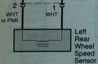 Inductive Wheel Speed Sensor |
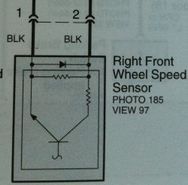 Active Wheel Speed Sensor |
The vehicle manual will also use a different symbol for inductive and active wheel speed sensors.
Step 8 - Set the wheel speed sensor type in the Traction Control module.
Only when using active sensors, open the Traction Control module and change the blue switch position.
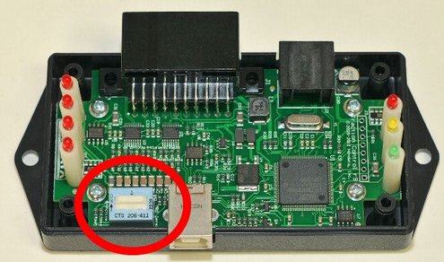
For inductive, hall effect and other sensor types the switch should be off (the white slider should be towards the outside of the circuit board). This is the factory default.
For active ABS sensors the switch should be on (the white slider should be towards the center of the circuit board). There may be a green plastic cover over the switch. In this case, peel away the green plastic to change the switch position.
Step 9 - Wire the Traction Control module to the wheel speed sensors.
Wheel Sensor |
Traction Control |
Left Front + |
Blue |
Left Front - |
Light Blue or Yellow |
Right Front + |
Green |
Right Front - |
Light Green or White |
Left Rear + |
Brown |
Left Rear - |
Tan or Gray |
Right Rear + |
Violet or Purple |
Right Rear - |
Pink |
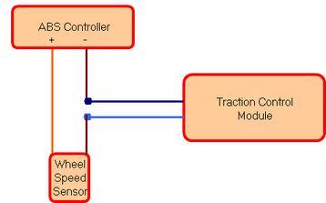
Inductive ABS sensor Wiring
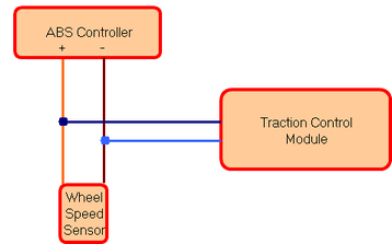
Vehicles without an ABS controller can wire the wheel speed sensors directly to the Traction Control module. Vehicles with an ABS controller need to wire the Traction Control module in parallel with the wheel speed sensors.
Inductive Wheel Speed Sensor Wiring
Working on one pair of wheel speed sensor wires at a time, remove some of the plastic insulation from each wire. This is easiest to do with a sharp knife or razor blade. It is best to remove the insulation in a different place on each wire (about 1" / 3 cm apart) so that, even if the insulation fails, the bare wires cannot short out. You only need to remove enough plastic insulation to expose the copper wire.
Strip the ends of the Traction Control wiring harness. With a soldering iron 'tin' both the Traction Control wiring harness wires and the vehicle wheel speed sensor wires which were bared above.
Join the Traction Control wiring harness to the wheel speed sensor wires by holding together and applying heat with the soldering iron. Make sure the connection is secure.
Insulate the join with tape. Self amalgamating tape is recommended, as it will stay water-proof.
When finished use a zip-tie to bind the vehicle wiring and Traction Control wiring harness together to prevent any strain on the soldered joints.
Active ABS sensor Wiring
Active ABS sensors need to be wired in series with the Traction Control module. The Traction Control module should be connected to the negative side of the wheel speed sensor wiring.
Active Wheel Speed Sensor Wiring
Identify the negative wire from the wheel speed sensor. Cut the wire, strip and join to the Traction Control module input. The polarity of the wires from the Traction Control module is not important. Solder the joint and use heat-shrink to ensure a water-proof connection, then use zip ties for strain relief, and finally protect from abrasion with electrical tape.
Step 10 - Test the Traction Control sensor inputs.
Spin each wheel in turn, and check that the Traction Control module wheel speed lights flash for each wheel. Normally you do not need to spin the wheels very quickly for the Traction Control module to pick up the wheel speed. Vehicles with active ABS sensors will need the ignition on to get a signal from the ABS sensor.
Step 11 - Configure the Traction Control module.
See the Vehicle Setup, Slip Setup and Output Setup sections of the Traction Control help file.
Normally the factory default settings will get you started, but the ABS sensor pulse count should be set for each vehicle.
Step 12 - Configure the ECU software.
See either the SManager / KManager / FlashProManager help file or the ECU Integration section of the Traction Control help file.