The Hondata CAN Boost adds support for aftermarket boost control over CAN for the 2012-2014 Civic Si. The following section will explain how the boost control parameters work in FlashProManager.
Duty Cycle
To control the solenoid a square wave is sent to the solenoid. Due to the impedance of the solenoid and frequency of the output this square wave results in a progressive opening (or closing) of the solenoid The solenoid will have an effective range, outside which changing the duty cycle will not affect the solenoid opening. For most solenoids this is 15% to 85% duty cycle, so it not recommended to operate the solenoid outside these limits. When the settings are configured for a normally open solenoid the actual duty cycle is inverted so that a higher duty cycle will increase boost.
Enabling Boost Control
![]()
The enables the boost control output.
Solenoid Configuration
![]()
There are two types of solenoid - normally open and normally closed. A normally open solenoid (like a GM solenoid) will give maximum boost at 0% duty. Note that in this case FlashProManager inverts the duty cycle so that in FlashProManager 0% duty cycle is minimum boost, and 100% duty cycle is maximum boost. It is important to set a boost limit as a solenoid or wiring failure will result in maximum boost. A normally closed solenoid will give maximum boost at 100% duty.
Activation Pressure
![]()
Since you do not need the boost control solenoid running all the time, the solenoid will activate above a certain manifold pressure. It is best to set this pressure slightly over atmospheric pressure.
Frequency
The frequency of the solenoid control output waveform can be set from 10 - 100 Hz. This will affect the boost level and the maximum amount of boost which the boost controller can generate.
![]()
Most solenoids operate best from 10-60 Hz.
Minimum and Maximum Duty
![]()
Sets the minimum duty cycle.
![]()
Sets the maximum duty cycle.
Quick Spool
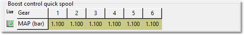
This tables opens up the boost control solenoid completely and closes the waste gate to build up boost faster. Once the pressure reaches the value in the table the solenoid goes back to its normal duty cycle. When using this feature, we recommend setting the solenoid activation pressure to 1 pound of boost, and the quick spool pressures to 1 or 2 pounds below target boost levels. To disable quick spool, set the values in the table lower than the solenoid activation pressure.
Air Temperature Compensation
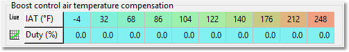
The boost pressure for a given duty cycle will vary with ambient air temperature, with increased pressure with cooler air and less pressure with hotter air. This table allows you to adjust the duty cycle based on intake air temperature. The compensation is applied to both a fixed duty cycle and duty cycle by rpm & gear.
Throttle Position Compensation
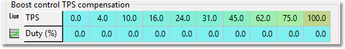
This table allows you to adjust the duty cycle based on throttle pedal position.
Max Boost by Speed
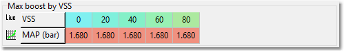
This table allows you to limit the boost pressure at different speeds. If the manifold air pressure exceeds the limit set in the table for a given speed, the ECU will set the target boost to the value selected from the table. Once the manifold air pressure drops below the limit, the target boost is selected from the boost control target boost table.
Boost Control PID Disabled
The boost control target boost and boost control duty feed forward tables are used to tune the boost control. These are advanced tables, knowledge of PID control and the way feed forward tables work is required. With PID disabled, the boost control target boost table will allow you to set the desired boost pressure by gear and RPM. The value selected from this table is in units of bar.
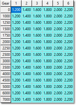
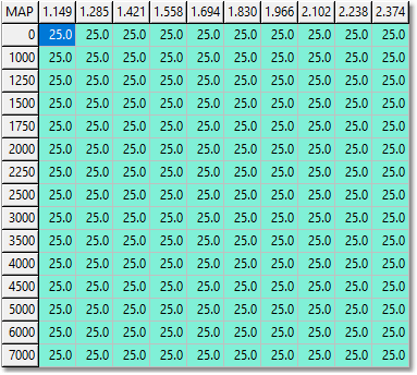
You can then use the boost control duty feed forward table to set the duty cycle for the desired boost pressure and RPM. The value selected by the ECU from the target boost table will be used as the x-axis input for the duty feed forward table.
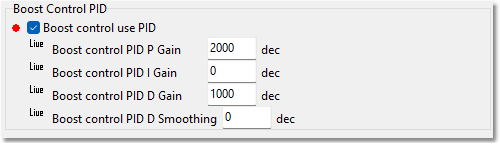
Boost Control PID Enabled
With PID disabled it is possible that the desired boost pressure will not be achieved with the duty cycle given in the duty feed forward table which will require more precise tuning. Enabling PID, the duty will be selected from the tables as described before, but the ECU will continuously add/subtract duty percentage until the desired boost pressure is achieved. The amount added/subtracted will be based on the PID parameters. (Note: the I and D Smoothing parameters are very sensitive. Only modify if necessary and if you know what you are doing).